






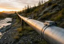
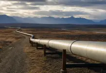








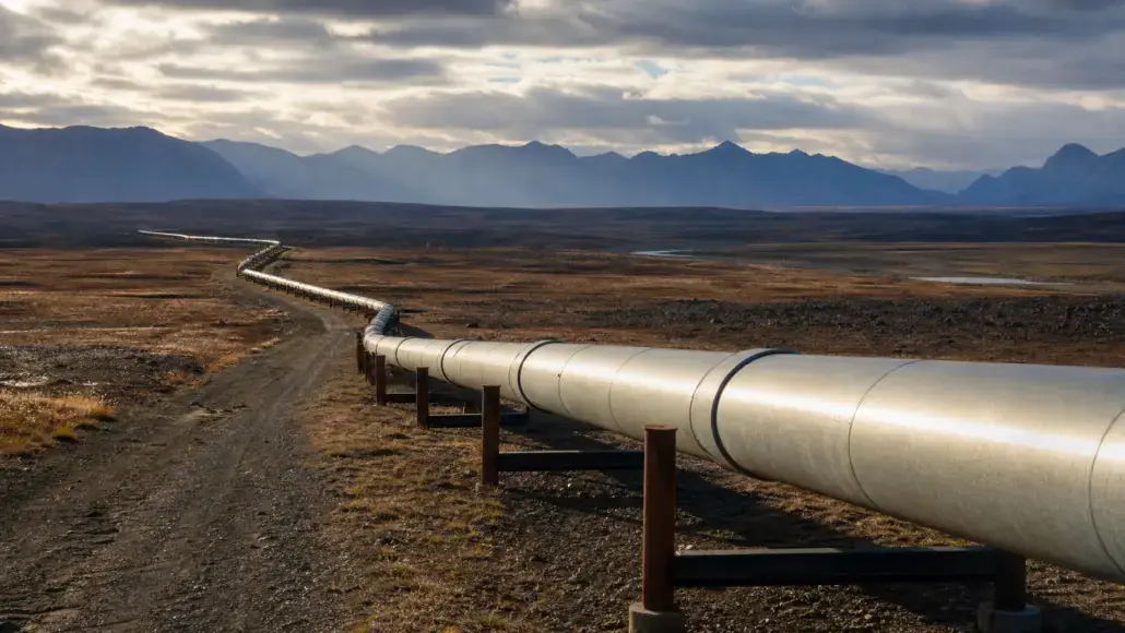
Buried energy pipelines represent some of the most capital-intensive and logistically challenging assets to inspect across global infrastructure networks. While line pipe buried in rural rights-of-way can periodically accommodate internal diagnostic tools, significant portions of pipeline mileage remain unpiggable due to tight-radius bends, low operational operating pressures, diameter transitions, or missing launcher and receiver traps. Even on piggable lines, critical segments passing beneath interstate highways, railway embankments, river crossings, and industrial plants cannot be excavated for direct visual examination without catastrophic civil disruption and permitting delays.
When operators must evaluate the external and internal condition of inaccessible pipe sections without digging extensive trenches, long range ultrasonic pipeline inspection provides an effective non-destructive screening solution. By deploying specialized transducer collars at a single local excavation point, technicians send low-frequency acoustic energy tens of meters along the pipe wall in both directions. The reflected signals reveal volumetric wall loss, severe pitting, and mechanical anomalies hidden beneath heavy soil cover.
Principles of Guided Wave Propagation and Modal Selection
Unlike conventional ultrasonic testing, which transmits high-frequency compressional waves perpendicular to the pipe surface to measure local wall thickness, long-range systems generate guided waves. These acoustic waves propagate along the longitudinal axis of the pipe, using the internal and external surfaces of the steel cylinder as a cylindrical waveguide.
The physical mechanics rely on low-frequency excitation, typically between 15 kilohertz and 100 kilohertz. Operating at these lower frequencies prevents rapid attenuation and keeps wavelengths significantly longer than the nominal wall thickness of the pipe. As the wave packet travels down the pipe, any change in cross-sectional acoustic impedance generates a reflected echo that travels back to the collar sensors.
Field engineers select specific wave modes based on environmental boundary conditions:
- Torsional wave modes, specifically the fundamental T(0,1) mode, which are non-dispersive across standard operating frequencies and remain unaffected by contained internal liquids.
- Longitudinal wave modes, such as the L(0,2) mode, which travel at higher velocities but interact with internal fluids, causing acoustic leakage into liquid hydrocarbons or water.
- Flexural wave modes, which develop when symmetric waves encounter asymmetric geometry changes, helping technicians determine the circumferential clock position of an anomaly.
Torsional mode excitation is the dominant choice for buried pipelines. Because torsional motion shears the pipe wall circumferentially without displacing fluid radially, energy does not leak into the transported crude oil or refined product, preserving signal range across active hydrocarbon lines.
Managing Acoustic Attenuation in Buried Environments
Applying acoustic screening to buried assets presents physical hurdles that do not exist on bare atmospheric piping. Soil compaction, moisture content, and protective pipeline coatings absorb ultrasonic energy, dampening wave propagation and shortening the effective inspection distance.
Viscoelastic coatings represent the primary source of attenuation. Heavy bituminous enamels, coal tar wraps, and thick multi-layer polyethylene coatings exert viscous drag on the oscillating steel surface. Depending on the coating chemistry and ambient ground temperature, signal attenuation rates in buried pipe can range from 0.5 decibels per meter on modern fusion-bonded epoxy up to 3.0 decibels per meter or higher on degrading asphalt coatings.
Acoustic range under buried conditions typically spans between 10 meters and 50 meters in each direction from the transducer collar. While this distance is shorter than the 100-meter reaches achieved on bare refinery overhead pipe, it easily covers the critical span of a highway crossing, a railway right-of-way, or a river casing from a single shallow bell-hole excavation.
Key operational strategies used to maximize signal penetration include:
- Selecting lower excitation frequencies, often between 20 and 32 kilohertz, where coating drag is less pronounced.
- Optimizing transducer coupling pressure through pneumatic bladders or calibrated mechanical clamping rings.
- Utilizing magnetostrictive sensor strips bonded directly to the pipe steel with rapid-curing adhesives when piezoelectric ring clearance is restricted.
- Removing loose soil and localized coating degradation around the transducer collar to establish clean acoustic transfer.
- Applying specialized baseline subtraction methods when repeated seasonal scans evaluate active corrosion growth rates.
In high-attenuation soils containing saturated clay or standing ground water, technicians frequently combine forward and backward scanning sweeps from adjacent excavation pits to eliminate blind spots under heavily loaded road embankments.
Industrial Standards and Defect Screening Sensitivity
Industry standards govern the qualification, execution, and interpretation of guided wave surveys. Documents such as ASTM E2775, ASTM E2930, and NACE SP0110 outline baseline procedures for screening buried carbon steel piping. Regulatory frameworks like the pipeline safety rules administered by the United States Pipeline and Hazardous Materials Safety Administration recognize guided wave ultrasonic testing as an accepted direct examination tool for external corrosion direct assessment programs.
Guided wave technology functions primarily as a screening tool rather than an absolute flaw sizing gauge. The system calculates reflection amplitude as a percentage of total cross-sectional area loss. Under favorable field conditions, long range ultrasonic pipeline inspection reliably detects localized metal loss exceeding 5% to 9% of the total pipe cross section.
Technicians categorize detected indications using standardized severity thresholds:
- Category 1 anomalies representing minor acoustic reflections under 10% cross-sectional area change, typically monitored during regular integrity maintenance intervals.
- Category 2 indications indicating moderate metal loss between 10% and 20% cross-sectional area change, requiring targeted follow-up scheduling.
- Category 3 severe reflections exceeding 20% cross-sectional area change, which trigger immediate exploratory excavation and local high-resolution ultrasonic thickness mapping.
Because structural girth welds generate predictable symmetric reflections of known amplitude, they serve as internal distance-calibration reflectors throughout the data record. By measuring the signal decay across successive girth welds, software calculates the specific attenuation rate of the surveyed pipe segment in decibels per meter, establishing a mathematical call-level curve for defect evaluation.
Next-Generation Guided Wave Sensors and Data Management
Recent technological developments have significantly expanded the diagnostic value of guided wave surveys. Advanced phased-transducer rings now incorporate independent circumferential receiver channels. By processing phase differences across sixteen or thirty-two distinct transducers around the collar, processing software creates synthetic focus points, generating unwrapped two-dimensional corrosion maps that pinpoint whether wall loss is concentrated at the vulnerable six o’clock position on the bottom of the pipe.
Field crews executing long range ultrasonic pipeline inspection increasingly utilize permanently installed monitoring rings on buried risers and critical road crossings. These compact transducer collars remain buried underground, connected to above-ground diagnostic cabinets where technicians can plug in test equipment annually without re-excavating the pipeline right-of-way.
Automated signal processing routines assist field technicians by filtering out coherent backscatter noise caused by minor surface roughness. Machine learning classifiers trained on thousands of confirmed excavation records compare reflection signatures against established libraries of weld geometry, branch connections, support clamp echoes, and corrosion patches, substantially reducing false excavation calls.
Aggregating screening echoes, wall-loss percentages, and GPS coordinates across hundreds of remote excavation bell holes requires structured Digital Inspection Management Systems for Oil and Gas Asset Integrity to eliminate isolated data silos and standardize engineering assessments.
Consolidating guided wave screening records into centralized integrity databases allows pipeline operators to track asset health across multi-decade operating horizons. Identifying subtle acoustic changes across repeat surveys provides an early warning mechanism, directing excavation budgets toward the highest-risk crossings while maintaining verified safety margins on buried energy infrastructure.
