
















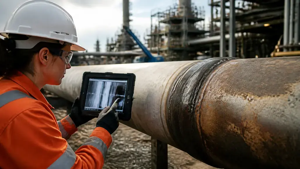
An ambiguous radiograph can leave oil and gas engineers weighing further inspection against repair.
This article draws on insights from FUJIFILM North America Corporation and its imaging expertise across film and digital inspection to explain how matching radiographic testing solutions to the asset focuses oil and gas radiography on a defined maintenance question.
Why Oil and Gas Radiography Cannot Be One-Size-Fits-All
Fujifilm’s oil and gas inspection guidance identifies corrosion and weld flaws among the conditions that testing can assess. An integrity engineer investigating wall loss in process piping should therefore define a different inspection objective from one evaluating a pressure vessel weld indication.
The plan should connect this objective to material thickness, component geometry and applicable acceptance criteria. With the inspection scope and acceptance criteria documented, engineers can interpret findings in context and recognize where the examination’s scope calls for further assessment.
Harsh field conditions make equipment uptime a factor in shutdown planning, while processing and image review also belong in estimates of inspection labor costs and downtime. Teams should establish where each activity will take place before mobilization so that scheduling accounts for the complete examination.
How Pipe Size and Wall Thickness Shape Technique Selection
The American Society for Nondestructive Testing describes the sensitivity of radiographic testing as capable of detecting thickness and density changes of about 1% along the radiation path. This describes sensitivity under suitable conditions, rather than a universal minimum detectable flaw size, so engineers should interpret it alongside the technique’s limitations.
For thin-wall, small-bore piping, planning should focus on the suspected wall loss or weld indication while confirming space to position the source and image receptor. The team needs to consider pipe diameter when positioning the image receptor and establishing the radiation path through the area of interest.
As wall thickness increases, exposure planning must account for the material along that path. The same society explains that technicians adjust X-ray exposure time and energy for the material, while component geometry and defect orientation can also limit what the image reveals.
A useful inspection request therefore pairs the component dimensions with a specific question about its condition. For suspected wall loss, the engineer should clarify whether the immediate goal is to screen for deterioration or to obtain measurements for further assessment. This provides the team with a stated screening or measurement objective to guide technique selection.
How Access and Suspected Damage Affect Method Choice
Before selecting equipment, engineers and inspection teams should confirm access for both the radiation source and image receptor. The following scenarios illustrate the placement and planning questions that deserve attention before mobilization.
- Single-side access: Conventional transmission radiography requires the source and receptor to be on opposite sides of the radiation path. Teams should confirm a workable arrangement around the pipe, since a digital detector alone does not change that access requirement.
- Confined spaces: Restricted working room makes early coordination with the site’s responsible safety personnel especially important. Equipment placement must accommodate the component while supporting the radiation protection plan.
- Offshore locations: Teams moving equipment into limited platform space should consider portability and plan for protecting equipment during transport and inspection. They should also establish where technicians will review images.
- Insulated piping: The request should identify the suspected damage and state whether insulation will remain in place. Technicians can then evaluate the planned source and receptor positions, as well as any access preparation required for the examination.
Access is only part of the question, because the limitations of conventional radiographic testing also include discontinuity orientation. A view intended to assess corrosion may need different planning from one intended to reveal a tight weld crack, and the team should define that objective before exposure.
The Occupational Safety and Health Administration describes the as low as reasonably achievable (ALARA) principle. Its ALARA guidance emphasizes time, distance and shielding, which teams should address within the available space rather than allowing scheduling pressure to dictate the setup.
Comparing Radiographic Testing Solutions for Oil and Gas Assets
Reliable radiographic testing solutions match the required image quality to the asset and field setup, whether the examination uses film, computed radiography (CR) or direct digital radiography (DR). For metallic fusion welds, the International Organization for Standardization covers both digital approaches in its guidance on digital detector selection.
Film requires development before a nondestructive testing (NDT) technician can interpret the image. Making processing arrangements is an important consideration when teams schedule an examination.
According to Fujifilm, CR uses reusable imaging plates that can flex around curved objects but require a reader to produce the digital image. Its comparison of radiographic inspection processes describes lower up-front costs than DR, while teams should include separate plate reading in turnaround estimates.
Fujifilm also mentions that DR is often the faster, more flexible option for larger defects. DR captures images with digital detector arrays for immediate field review, which can suit larger-defect inspections with demanding turnaround needs. The same comparison of digital inspection workflows also notes that both CR and DR avoid single-use film and processing chemicals.
A 2024 paper on radiographic image quality and noise identifies basic spatial resolution, specific contrast and signal-to-noise performance as key image-quality parameters. Engineers should discuss these measures with the NDT technician for the intended setup rather than ranking methods by defect size alone.
What a Properly Matched Inspection Means for Maintenance Decisions
Engineers should assess reliability and ruggedness by asking whether the proposed equipment and handling arrangements are suited to the field location. Portability deserves the same scrutiny, including how the team will move equipment into position.
For inspection throughput, the plan should identify where processing and image review will occur within the available inspection window. Radiation safety should remain a separate planning requirement rather than a trade-off for speed.
The Pipeline and Hazardous Materials Safety Administration tracks miles inspected by method for crude oil, refined petroleum and biofuel pipelines in its national pipeline performance measures reporting. The page reports performance data rather than prescribing a radiographic technique for an individual component.
At the component level, engineers need records that identify the inspected location and the area covered by the examination. Those records should preserve the acceptance criteria used to evaluate the findings and explain any limitations so the next assessment begins with a clear understanding of what the inspection established.
Frequently Asked Questions About Radiographic Testing Solutions
Choosing a technique means linking the maintenance question to the asset’s conditions. The following answers bring those considerations together for engineers planning oil and gas radiography.
What determines the right radiographic technique for a pipe or vessel?
Pipe size and wall thickness shape the setup, while access and suspected damage help determine whether the proposed view is suitable. The NDT technician should also consider required image quality and applicable examination criteria.
How does digital radiography differ from computed radiography?
DR captures images with a detector for immediate digital review, while CR uses reusable imaging plates. Those plates require a separate reader to produce the digital image, adding a processing step to the workflow.
Why does access to an asset affect inspection choices?
The proposed view depends on suitable positions for both the source and image receptor. Available working space also shapes equipment placement and the radiation protection arrangements needed for the examination.
How does technique selection support long-term asset integrity?
A defined objective gives engineers a basis for interpreting findings and planning follow-up assessments. Documenting the examination’s scope also preserves the inspected location and examination limits for the next assessment.
Turning the Right Radiograph Into a Confident Maintenance Decision
Matching radiography to the asset starts with a maintenance question and carries through field planning to interpretation. Engineers should carry the inspection findings and examination limits into decisions about further assessment, monitoring or repair.
